Dave Moulton

Dave's Bike Blog

Award Winning Site

More pictures of my past work can be viewed in the Photo Gallery on the Owner's Registry. A link is in the navigation bar at the top

Bicycle Accident Lawyer


Powered by Squarespace
Search Dave's Bike Blog


 Watch Dave's hilarious Ass Song Video.

Or click here to go direct to YouTube.


A small donation or a purchase from the online store, (See above.) will help towards the upkeep of my blog and registry. No donation is too small.

Thank you.

Join the Registry

If you own a frame or bike built by Dave Moulton, email details to list it on the registry website at www.davemoultonregistry.com

Email (Contact Dave.)

 If you ask me a question in the comments section of old outdated article, you may not get an answer. Unless the article is current I may not even see it. Email me instead. Thanks Dave

Entries in Framebuilding (38)

Tuesday
Mar062012

Back from NAHBS


The North American Handbuilt Bicycle Show (NAHBS) has grown to become a wonderful bicycle institution. Back when I was in business there was no such show, I had to attend the Interbike Show, and for a small business that was a challenge; it was not an inexpensive endeavor.

With the Interbike Show, apart from being extremely costly, a small framebuilder tended to get lost amongst all the glitz and glamour of the fancy lighting and displays of the industry giants.

The NAHBS is a show just for small framebuilders, and although a few exhibitors try to upstage the competition with a fancy display, NAHBS doesn’t have that “Disneyland” glitter and feel to it; all you see is product.

I went to the show to give support to my ex apprentice Russ Denny who was re-launching the Fuso line of bicycle frames. I also got to meet many old friends, some I had not seen since the 1980s.

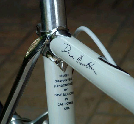
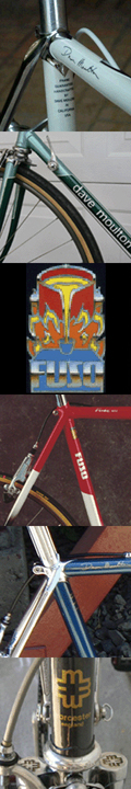
I first flew to San Luis Obispo to hook up with long time friend David Ball, and then we drove up to Sacramento for the show, taking with us the #001 Fuso (Built 1984.) that David owns. (Picture below.)

Excuse me if I diverse a little just to illustrate a point: David Ball is a highly skilled woodworker and has told me he would like to build guitars, but admits he would probably have to build fifty guitars before they were any good.

I see a parallel between highly skilled woodworkers who play guitar, and so try their hand at making guitars; and highly skilled metal working bike riders who are drawn towards framebuilding.

I can see David’s concern, what would be the point of making a beautiful guitar that showed off his woodworking skills if when you played it, it sounded like crap. All the exotic woods, and inlays of abalone and mother of pearl would mean nothing if it didn’t sound somewhere close to a Martin guitar which is considered the industry standard of excellence.

However, here is where my parallel ends. How many framebuilders would have the honesty to admit they would have to build fifty frames before one would be any good?

And do they really need to? Case in point; just this morning checking my emails after returning from California; there was one from an owner of a custom frame I built in the early 1990s.

His opening line, “I never built my lovely frame into a bike for fear I would use it, and God forbid ruin it.”

Here is a custom frame I built in Reynolds 753, that would ride and handle as good if not better than most, and this owner will never know the joy of riding this bike.

So you see there is a market out there for “Wall Hangers.”

There is also a market for bikes that people want to ride; which is what I told Russ when he expressed certain concerns he had about going to NAHBS in the first place. “How can I compete with someone who puts between 70 and 90 hours of labor into a frame?”  He told me.

My answer is, “You don’t.” The Fuso was always a bike to be raced and ridden, and this new Fuso is no different. The new steel tubing builds into a frame that is comparable in weight to other materials. Steel is practical for most riders; I can’t wait to get mine.

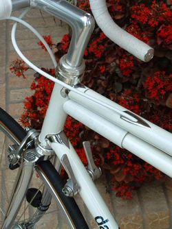
(Above.) Russ Denny on the right, with the New Twin Downtube version of the Fuso in the foreground.

The Fuso is still a hand built frame; it is just different enough to appeal to someone who doesn’t want to go with one of the massed produced, made in China brands. Its builder, Russ Denny has the background and experience that you can buy and ride the bike with confidence.

I saw metal craftsmanship and paint work at the NAHBS that was out of this world, I am not going to name names or even show pictures, because unless I could actually ride each one of them how can I judge a frame’s true value? I can’t simply pick it up and play it like a guitar.

When a craftsman can combine the beauty of his metalwork with the ride and handling qualities of what a bike frame should be; then he can with all honesty, call himself a framebuilder.  I hope I won’t be considered unkind for saying that.


Tuesday
Dec272011

Straightening steel forks

I came across a bike blog from Taiwan that happened to be linked to my blog; it showed a picture of a bike with a strange looking fork. The writer speculated whether it was a custom fork.

It was custom alright, but by accident rather than design. The rider had run into something solid, (Probably a car.) and bent the fork back.

To give this rider credit for ingenuity, it looks like he simply turned the fork around (Backwards.) and carried on riding.

Over the years I straightened many steel forks like this one, with complete safety and often not even damaging the paint. When you consider that a fork blade starts out as a straight tube; it is then rolled in a machine between rollers to make it tapered. This process is done cold.

The top end is pressed to an oval shape; this is also done cold. Finally the framebuilder cold bends the fork blade to the desired curve. So if the fork blade is bent once more in an accident, it can be re-straightened cold with complete safety as long as the tube is not kinked or rippled.

I would not recommend that this be done multiple times but once is okay. I will explain how it can be done.

My fork blade straightening tool was a piece of one inch steel (Sometimes called black iron.) gas or water pipe about four feet long. One inch pipe measures 1 in. dia. on the inside, and is about 1 ¼ in. on the outside. (Picture right.)

I also cut a 1 in. piece of this same pipe then cut it in half to form a “C.” This was then welded to the top of the four foot length of pipe, and would form a cup to go around the fork blade near the crown.

This was padded on the inside of the “C” with several layers of duct tape to protect the paint.

Next take a piece of old bicycle chain about 10 inches long, make a loop by joining the ends using a chain rivet tool.

The fork needs to be removed from the frame; hold the steering column horizontally in a vise that is solid and won’t move.

Position the bent fork blades so they are sticking out horizontally on one side of the vise; left or right depending on which hand you use. Right side if you are right handed.

The fork should also be positioned so the blades are one above the other, and the bend that you are about to straighten is away from you.

Straighten one blade at a time by placing the chain loop over your four foot piece of pipe, and the other end of the loop over the fork tips. Place the “C” cup up near the crown above the bend, hold in place with one hand, and pull towards you with the other hand to straighten. Repeat to straighten the other blade.

Now you will need to align the fork. I had a surface table with a fixture to hold the fork. However, most people will not have this luxury, so here is the next best thing. You need to make or have made another tool consisting of a piece of 7/8 inch solid steel bar, about 24 inches long. (Picture left.)

Turn down in a lathe 18 inches of this bar to a smaller diameter, about ½ or 9/16 of an inch. (Leaving 6 inches at 7/8 dia.)

It does not have to be exact as long as it is small enough to pass easily through the butted end of the steering column. 7/8 in. is the diameter of a quill stem. (I am assuming this is an older steel frame with a one inch steering column.)

Slide the 7/8 in. portion into the steerer with the smaller diameter length reaching down between the fork tips. You now have a reference point that is dead center of your fork.

Ideally place a front wheel spindle between the fork tips, but failing that you can use a piece of steel bar 5/16 or 9mm. dia., or even a pencil at a pinch.

The fork tips need to be 100mm. apart, (Measured on the inside.) and centered on your special steel bar you have placed in your steerer.

The fork tips need to be in the same plane as the fork crown; a straight edge across the fork blades up near the crown can be sighted with your wheel spindle, or whatever you have between your fork tips. The fork rake or offset can be measured from the bar to the wheel spindle.

Also the straight part of the fork blades before the curve starts can be checked by placing a straight edge on both the front and back of the blades to see if the steel bar is centered.

In a front end shunt like this, the top and/or downtube sometimes get rippled. If this is the case the tubes need replacing as they will eventually break. The good thing about a steel frame is that it will rarely fail suddenly, but a crack will appear first and the frame will start to feel “spongy” as a warning before it fails completely.


Thursday
Nov182010

Building small frames

Frame design, in many ways, was much simpler when I was building back in the 1980s.

Top tubes were always level; it was not acceptable, to me or my customers, to build a frame with a sloping top tube.

Once a rider had established his correct frame size, he set the handlebar stem about 4 or 5 centimeters above the head bearings.

Then he set his saddle to the correct height and he was for the most part, good to go.

The handlebar stem could be adjusted a centimeter up or down as the rider wished.

The other point that made everything simpler was the fact that a person could go buy a frame of any make, in the same size, and the seat to handlebar height ratio would be the same.

If the top tube length varied slightly it could be corrected with a longer or shorter stem. Handlebar drop never even entered into the equation because it was automatic once you had the frame size right. The level top tube was in fact a point of reference.

Many years before I started riding, the wheel size for a racing bicycle was set at 27 inches diameter, or 700c as it is known today. This means that there is a fixed distance from the ground to the bottom of the head tube. This is always the same for any size frame with 700c wheels.

On a level top tube frame, it doesn’t matter that the builder changes the bottom bracket height. If he raises it, and the seat tube length remains the same, then he also raises the top tube and the head tube becomes longer. This is because the bottom of the head tube remains in a fixed position.

The rider’s saddle height is measured from the pedals (Or BB center.) to the top of the saddle. So although the rider is sitting higher because of the high bottom bracket, because the head tube has become longer by an equal amount, the seat to handlebar height difference always remains the same for any given size.

Each frame size will have its own saddle to handlebar height difference, which increases as frames become larger, decreases for the smaller sizes. On a modern sloping top tube frame, raising or lowering the bottom braket height will not necesarily alter the head tube length.

With today’s design, the bottom of the head tube is still in a fixed position, but the top of the head tube can be anywhere; it is not governed by a level top tube as it used to be. There seems to be no standard point of reference between the different manufacturers.

Where today’s design has an advantage it is in building very small frames. The bike pictured top left, is my personal bike; it is a 51 centimeter. (Center to top.) You can see in the picture that if the position of the bottom head lug is fixed, a framebuilder can only lower the top tube another 2 cm. and the lugs merge. To all practical purposes a 49 cm. is the smallest level top tube frame he can build.

The only way to go smaller is to shorten the seat tube by raising the bottom bracket. This really goes against the requirements of the rider, because the last thing a person with short legs needs is to be higher from the ground.

I was asked just this week how would I go about designing frames for women. If the woman was 5’ 4” or taller it was no problem; I would just build according to the customers measurements as I would for a man.

If the woman was less than 5’ 4” then it was not so much a case of building a frame to fit, but one of how small can I build this frame? There is not only a limit to how short can I make the seat tube, but there is a limit the how short one can make a top tube.

The whole problem is fitting two large wheels into a frame that has reached the limit for those size wheels; it restricts what you can do. Smaller wheels are available but rims and tires are limited to a much narrower choice than for the standard 700c.

Frames are now sized like tee-shirts; extra-small, small, medium, and large. My advice to female under 5’ 4” would be to buy a frame in the smallest size possible. There will be no problem with the seat tube length, and there is now a far wider range of handlebar stem lengths and angles than were ever available in my day.

With this wider range of handlebar stems, it should be possible for most riders to dial in a near perfect position. The only problem as I see it is that another dimension has been added to the equation, and that is handlebar drop.

In the old days one only had to concern themselves with saddle height and reach, drop took care of itself with the correct size frame.

I always maintained that a rider’s arms (On the drops.) should be in direct opposition to the legs. Choose a combination of drop and reach that will achieve this. 

Back in 2007 I wrote an article which included a chart that gave a drop measurement and was based on my old fit philosophy from the days when top tubes were level. Some people have found it useful.

Your comments and input as always are appreciated.


Tuesday
Oct122010

Brake cable tunnel 

A brake cable tunnel through the top tube was an optional extra that I offered initially on my custom frames, it included a shield shaped re-enforcing plate where the slot was cut in the tube.

This thin steel plate brazed in place was mainly for decoration, and was often chromed as shown here. Structurally it was unnecessary and later when I offered the tunnel as an extra on the Fuso I dispensed with the little plate.

Had I simply cut slots in the top tube to thread the cable outer housing through, then some form of re-enforcement would have been necessary, as the top tube would have been considerably weakened by cutting slots in it.

I did not like this approach as moisture can enter through the slots causing corrosion inside the top tube. I made my tunnels a self contained and sealed unit.

I did this by first cutting the slots. Then I took a thin steel tube with a hole just big enough for the brake cable inner wire to slide through, bent it to a curve, then after measuring the length I brazed a short piece of a larger diameter tube on each end of the first tube.

This assembly was then threaded through the slots and was brazed into place; in the case of a custom frame the shield-shaped decorations were added at this time.

Then with a hand held drill and a drill bit just slightly larger than the outside diameter of standard brake cable housing, the tunnel entrance was drilled out from either end. See drawing below.

Finally, the surplus tube was cut off and filed flush with the outside of the top tube. Or in the case of a custom frame, flush with the re-enforcing plate. See the following illustration.

With this system the cable housing went from the brake lever to just inside the front end of the tunnel; the bare wire went through the thin steel tube, and another short piece of cable housing went from the rear exit point to the rear brake.

It did however call for some maintenance. Although no moisture could enter the top tube, the cable entry point could collect water as it drained down the outer cable.

Customers were advised to keep both the inner wire well greased to keep friction down, but also to grease the cable housing where it entered the top tube, to keep moisture out.

Even on the custom frames with chrome as shown here I would still advise plenty of grease at the entry points.

Unfortunately I have noticed some frames with tunnels that have a creeping rust problem from inside the hole to the outside surface of the top tube.

This would have to be pretty bad to become a structural problem, because of the way the tunnel tube was assembled as described here.

If you have this problem, unless you are planning on a complete repaint; I would advise to clean the surface rust down to the bare metal, treat with Navel Jelly, and touch up paint.

Let the paint dry thoroughly, and then apply plenty of grease as previously described. You might also consider using some clear silicon sealer at the entrance point. (The type of sealer used in kitchens and bathrooms.)

Fill the entrance hole at both ends with silicon; assemble the whole thing complete with inner wire. When the silicon is dry, remove the inner wire, grease thoroughly and replace.

But remember, paint and silicon don’t mix, and neither will silicon and grease, so take your time and do one step at a time. Allow paint to dry, then allow silicon to dry and then ad grease to the inner wire.


Thursday
Feb142008

Framebuilding FAQs

I received two emails last week with questions on framebuilding. I don't have the time to go into lengthy instructions on how to build a frame, however, I thought I would post my answers here, that way others might find it useful.

I am hoping other readers will find it interesting to know some of the aspects of putting a frame together.

One question was, "Where do I start, do I need to build a jig?" A jig is simply a fixture to hold the tubes in place during assembly, it speeds production if you are building a number of frames all the same.

The frame is not brazed in a jig, for several reasons. The jig would suck up all the heat and take it away from the area you are trying to braze. The jig would obstruct access to all parts of the joint. Metal expands as it is heated and contracts as it cools, if the tubes are firmly clamped in a jig all manner of distortion will take place, and misalignment and built in stresses will be the end result.

The picture that permanently heads this blog is of me tack brazing a frame in a jig. I am heating and brazing tiny spots, just enough to hold the tubes in place. Then the frame is removed from the jig, checked for alignment and held in a vise, with a wooden block around a tube to prevent damage. As the frame is fully brazed the tubes are free to expand and contract as they will.

Jigs only came into wide use in the 1960s, prior to that most framebuilders assembled and pinned the frame together by drilling a small hole through the lug and tube, and inserting a short piece of wire or small nail. The frame was then usually hearth brazed; that is a hearth of hot coals, or one made of fire bricks with the heat applied with a hand held torch. (Picture left.)

With hearth brazing there is less distortion because the whole joint is heated uniformly. For example, the whole bottom bracket shell, seat and down tubes, and in some cases, the chainstays are all brazed at the same time.

The drawback with hearth brazing is that you heat the tubes several inches away from the joint and thereby anneal or soften the tubes. The method I used was to braze with a hand held torch that had a smaller but more intense flame. Working quickly, I could pin-point the heat on the lug only heating the tube barely a quarter of an inch (6mm.) from the lug. This way the tubes retained more of their inbuilt strength, resulting in a stiffer more responsive frame.

On the downside this method causes more distortion. However, by always following the same procedure and sequence, I got to know which way the frame would distort. I would start off with the frame out of alignment, so it would end up in alignment after it was brazed.

When the lug and tube are initially heated they are two separate pieces of metal so not much distortion takes place because the two can move independent of each other. Once you flow brass into the joint the two become one. As the metal cools it contracts and the metal shortens in length so it will pull in that direction. If I begin brazing at the back or center of the lug; there is little or no tube movement at this point because the whole is a triangle holding itself in place.

Then moving clockwise to the left, as the left side cools it will pull to the left; it is still moving to the left as I work my way around to the right. It will move a considerable amount because the right side is not yet brazed and the tube is free to move. By the time I get to the right side and joint is finished; as it cools it will pull back slightly to the right, but not as much because the left side has already cooled and is solid.

So you can see that the tube needs to be slightly offset to the right to compensate. I cannot tell you by how much because it depends on the speed of the operator and the amount of heat used.

As for brazing the rear triangle. I would finish and clean up the main triangle, then assemble the rear triangle separately, by brazing rear dropouts into chainstays, and next the seatstays to the rear dropouts. Then cut to length and braze the top caps to the seatstays. After clean up, I would then braze the rear triangle to the main triangle.

The same alignment problems exist for the rear triangle. If I tack braze the right side first, it is already contracting as it cools and the wheel center is moving to the left. (Viewed from the rear.) Now when I braze the opposite left side one would suppose that it would then contract as it cools and the wheel center back to center, but this is not the case. Because when I tack braze the right side, the left side is preheated so brazing the second side takes less time, and the left side contracts at a lesser rate.

Again the wheel center has to be set slightly to the right to compensate. When the initial tack has been made and allowed to cool; if the wheel center is off, the tack can be reheated to a dull red. This is not enough to melt the tack, but the brass becomes plastic at this temperature and can be moved in the desired direction to bring it into alignment. Bearing in mind that it will again contract on cooling so it is again necessary to over compensate. Once alignment is correct the seatstay caps can be fully brazed to the seat lug and the rear triangle will stay aligned because each side will expand and contract back to its original position.

I did not pin my frames, I assembled and tacked them in the jig and my brazing method did not allow the tube to move, because part of the brazing was cooling as I moved around the joint. It is only necessary to pin if you have no jig, or if you are going to heat the joint completely in a hearth and the tube might move as a result.

I also used my jig as a design tool; I could set up the jig to see if a design was feasible before I even started cutting tubes to length. Today you can do the same thing on a computer, making a jig unnecessary if you only plan to build one frame. It might be a good idea to do a full size drawing on a sheet of plywood or sheetrock, or at least a chalk outline on the floor so you can lay the frame on it for reference as you progress.

Some of the old time framebuilders used to braze the head tube to the down tube first using the bottom head lug. By measuring the angle with a protractor and ensuring this was correct to the drawing, everything else would fall into place.

Pinning the frame alone will only ensure that the tubes do not slip in or out of the lugs, the whole assembly will flop around like a jointed wooden puppet. You will need to braze each pin in place, in other words tack it. Then you can check for alignment, and the tubes will move on the pin and tack and stay where you place them. This brings me to the second question I was asked.

Why pin in the center of the frame? Could a pin be placed in the side of a bottom bracket for example. I have already explained if you tack on one side the tube will move in that direction as it cools. You would have a hard time realigning the frame as it would always have a tendency to move towards the original tack. Pinned and tacked in the center, you can move the tube either way to align it.

How about a pin on the right side of the bottom bracket to hold the tube as you braze the left side? Not a good idea. As the left side cools it will still pull to the left, and the pin will now be under stress. As soon as you apply heat to finish brazing, the bottom bracket shell will crack.

Should you use brass of silver? I always used brass, as did most European builders. Brass is easier to use, it melts when the metal is orange-red. If you go beyond to yellow you are too hot. Heat is controlled by constantly moving the torch. Even if you use silver, you will still need brass to braze the dropouts into the chainstays, etc, as silver is no use for filling large gaps.

A question I know will be asked. Why do I have a small hammer in my right hand along with the brazing torch? (Top picture.) If there is a small gap in the lug as I braze, I switch the torch to my left hand and keep the heat applied as I tap down the edge if the lug with the hammer. Then switch back and continue brazing.

There is a previous article I wrote on simple frame repairs, replacing tubes in a damaged frame is a good way to practice and learn framebuilding skills. I also mentioned some frame design software here.