Dave Moulton

Dave's Bike Blog

Award Winning Site

More pictures of my past work can be viewed in the Photo Gallery on the Owner's Registry. A link is in the navigation bar at the top

Bicycle Accident Lawyer


Powered by Squarespace
Search Dave's Bike Blog


 Watch Dave's hilarious Ass Song Video.

Or click here to go direct to YouTube.


A small donation or a purchase from the online store, (See above.) will help towards the upkeep of my blog and registry. No donation is too small.

Thank you.

Join the Registry

If you own a frame or bike built by Dave Moulton, email details to list it on the registry website at www.davemoultonregistry.com

Email (Contact Dave.)

 If you ask me a question in the comments section of old outdated article, you may not get an answer. Unless the article is current I may not even see it. Email me instead. Thanks Dave

Entries in Framebuilding (38)

Monday
Apr112016

Minimalist

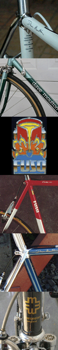
I always took the minimalist approach to frame design and building. Less is more, and why do more than is necessary, especially if it doesn’t improve the end product. My bottom bracket gear cable guides were an example of this. 

On my custom frames I filed two grooves with the corner of a square file, brazed a piece of wire across the groove, and then drilled a hole through. (See picture above.)

When I started production on the John Howard frames in 1983 and the Fuso a year later, I simplified the procedure. I filed two grooves with a small round file, took a short piece of automotive steel brake fluid line and brazed it in the groove, finishing it off by chamfering the edges with a hand held belt sander. Very simple and it did the job. (See below.)

There were always critics who questioned, “Isn’t it a bad idea to have the bare cable touching the paint.” To which I answered:

Unless the frame is chrome plated, cables have always and will always touch paint somewhere.

If I brazed a channel that covered the whole area where the cable went around the bottom bracket shell, it would then be painted and the cable would still run on the paint. It would take longer to produce, look ugly, and not really improve anything.

Throughout the 1970s gear cables were run through cable guides that were brazed to the top of the bottom bracket. These were of course painted along with the rest of the frame, and the cable ran on the paint, which is why I knew it would be okay. The cable runs in one position and the constant movement of the cable prevents it rusting. (See below, a 1972 Italian Masi.)

The cable guides on top of the bottom bracket collected dirt and made it harder to keep the bike clean in that area. By the 1980s framebuilders realized a neater and much simpler idea was to run the cables under the BB. It has been pretty much standard practice ever since.

So fast forward to today, or to be precise the end of last week.

Someone on Facebook questioned the cables running on the paint.

Why didn’t I do it this way? With a picture (Right.) of someone else’s frame. 

As usually happens on the Internet others chime in with comments like, “Oh yea, that always concerned me too.”

Next I find myself writing lengthy explanations, getting really annoyed that I am having to justify something I did 30 years ago. Then I realized people send me pictures of the underside of the Bottom Bracket with the frame number stamped on it. I always save these pictures so I pulled up several from my archives.

Fuso frames numbering from 020 (Above.) to 693, old frames built from 1984 to 1986. All with original paint, some with the bare frame with the cables removed, showing surprising little wear at all. They say a picture is worth a thousand words, and it is true in this case. I have about 8,000 or 9,000 worth here.

So if this is something that has concerned you in the past, look at these pictures and realize you are worrying about a problem that doesn’t exist. The latter frames shown had BBs made by the Japanese Takahashi Company. These had the cable guides cast in the shell and I didn’t have to do a thing. The others were finished in the manner described earlier.

I am always willing to answer questions about my framebuilding practices, but please use a little respect and tact when doing so. When someone asks “Why did you not do it this way?” it is a direct insult, and implies I didn’t know what I was doing.  

Footnote: The plastic cable guide (Left.) was not in general use in 1983 and 1984 when I began production of the John Howard and Fuso frames.

In 1985 I used it on the Recherche frames, it saved a lot of time and ended the controversy of cables running on paint.  


  To Share click "Share Article" below

Monday
Feb012016

The Importance of a Paint Facility

One of the largest outlays in setting up a framebuilding business is a paint facility, by that I mean to include a totaly enclosed, dust free paint booth.

It is a large expense to set up and maintain, because it takes up a lot of space. It therefore it prohibits one from working out of their home, or some tiny hole-in-the wall shop. In most places you can’t spray paint in a residential neighborhood anyway. You have to own or rent space in an industrial area.

Rent is a huge overhead when running any business. It is the reason I eventually went out of business in 1993 when the demand for road frames dropped to a level where I could not generate enough income to pay the rent on a 1500 sq. ft. industrial unit.

I could have maybe squeezed into a 1000 ft. space, but the rent would not have been that much lower, plus I would have had the expense of moving, costing money I didn’t have.

My paint booth was totally enclosed, it measured 20 x 20 feet. That is 400 sq. ft. and with at least a 3 foot space required all around it, you can maybe appreciate that any space under 1500 sq. ft. for the rest of the shop would be a squeeze.

At one end of the booth was a large fan that drew the air from inside the booth and exhausted it through a 2 ft. diameter vent through the roof. The air was drawn through replaceable filters that caught the paint over-spray.

 At the opposite end of the booth were air intake filters. These were “Sticky” so they caught dust and prevented it from entering the booth. The booth had a partition inside, one side to hang frames being painted, the other side was where the painting took place.

The partition prevented frames waiting and those just pained, and therefore still wet, from getting over-spray on them. I also had an electric paint curing oven that baked the paint to 250 degrees. This was another essential piece of equipment, as It allowed paint to be sanded for the next coat in an hour or so, rather than wait a day or more for it to air dry.

Owning a similar facility with a paint booth, is also the reason why I never started up again years later when the demand for road frames picked up. My shop cost $30,000 to set up in 1983, today that figure would be closer to $100,000. Too large an initial outlay, with no guarantee I would ever see a return on the investment.

Is it essential to have a paint facility? I am often asked. The answer is no, but it is for me. Many framebuilders build frames and ship them somewhere else to be painted. But the paint job is more than half the profit in building a frame.

To me, the paint is as important as the building of the frame, and the two go hand in hand. The paint is what the customer sees, it is too significant to be left in the hands of some outside entity. I would never build frames and not have total control over painting them.

There is the cost of shipping the frames both to and from the painter, and there is also the time factor. When you have your own facility you can handle a rush job easily. Mistakes and flaws can be fixed immediately, and even a complete strip and re-paint is not the end of the world.

The one drawback is, you have to produce enough frames to warrant the expense of owning your own paint facility. One or two frames a week won’t cut it. Initially I painted myself, but at the height of my production in the mid-1980s, it became necessary to train and employ a full time painter. I produced as many as 30 frames a month. It was a good and profitable business.

When the demand dropped below 20 frames a month, I could lay off employees, but I still had the rent and overhead on the fairly large industrial space. Times have changed. In the eighties if you wanted a top of the line bicycle frame, it was hand brazed, lugged steel.

Those days are gone forever, and it is the reason why builders like Ben Serotta, myself and others are no longer building frames. And really I do not need to build anymore frames, there are thousands of them still out there. They come up for sale ever week on eBay and Craig’s List, many of them hardly used and still in mint condition.

Even on frames that have had a lot of use, the paint has held up well, which speaks volumes for my always having my own paint facility.


  To Share click "Share Article" below

Monday
Dec142015

When steel frames fail, and why

My last article drew the following comment that gave me food for thought:

I have seen a frame fail at the downtube shifter braze-on. The down tube was installed backwards, the short butt was at the top so this braze-on was installed in the thin center part of the tube. It weakened it enough that it buckled there.

First let me explain that the down tube in this case was not necessarily installed “Upside Down.” Double butted tubes are so-called because they are butted at either end. The butt at one end is longer. That is the end that is cut shorter when building smaller frames.

So yes, if the framebuilder was building a large frame and using the full length of the tube, he could put the long butt at the top, but this would not necessarily be normal practice.

In a production setting, which included small batch production like the Fuso, the down tubes would be pre-mitered at the top end, because that angle was the same across a range of sizes. The long butt was left at the bottom bracket end so it could be cut later to accommodate whatever size frame I was building.

Incidentally, a simple way to tell which end has the long butt, is to balance the tube on a finger in the center. The longer butted end is obviously heavier. Tubes are also usually marked with the maker’s name or trade mark on the end that is not cut, but these marks can get stamped on the wrong end, so best to double check.

The short butt is usually 3 or 4 inches of the heaviest wall thickness, then it tapers down gradually for 3 or 4 more inches to the thinnest part in the middle of the tube. So the gear lever boss would not normally be on the absolute thinnest part of the tube, and even if it was, under normal circumstances it shouldn’t fail.

The commenter mentioned that the tube buckled. This usually means the bike had a front end shunt at some point, and it does not have to be a serious crash. I remember one time in the UK, I built myself a brand new cyclo-cross frame. The first time out I dropped my front wheel in a mud hole, and did a spectacular vertical stand on my front wheel.

I did not go over the top, but simply fell over sideways. Later I noticed the down tube was buckled right behind the bottom head lug. Once a tube is rippled, it will crack and eventually fail.

Barring such accidents a good steel frame will last fifty years or more. Ridden hard enough and long enough metal fatigue will eventually cause it to fail. But how many frames are ridden that hard and that long? Although sometimes a tiny crack can happen during building.

Metal like wood has a grain. Actually nothing like wood, but the only reason I draw that parallel is to remind me that wood will crack or split along the grain, whereas metal will usually crack across the grain.

When metal cools from its molten state, it forms a crystalline structure. Steel is then often cold rolled into bars or sheets. Wire and tubes are drawn though dies. Either process crushes and elongates the crystals in the metal forming a grain that runs along the length of the bar or tube. This actually strengthens the metal. (See above picture.)  

I found from experience that damage can be done to the very thin bicycle tubes, not only by overheating, but more often than not, by heating cold metal too quickly. Overheating while brazing causes the brass to flow in between the crystals of the steel, thus weakening it greatly. However, for this to occur the metal would have to be white hot and in the verge of melting.

More common is heating too quickly and this often happens when tacking a frame together. The metal is cold, and the framebuilder comes in with a small, hot flame to put a little blob of brass to hold the tubes in a lug, or a part like a brake or chainstay bridge.

Metal expands when it is heated, but if the metal is heated in one tiny spot, the surrounding cold metal will not expand and a minute crack can form, often so tiny it cannot be seen with the naked eye. The crack can fill with brass and may not fail until many years down the road.

My advice. Preheat the area first, and always tack at a point where the grain in the tube is a 90 degrees to the component part you are tacking. Not parallel with the grain. (See picture above.) Follow this simple rule and there will be less chance of a tube cracking.

This really applies to the initial tacks when the metal is cold. After two or three tacks and the metal warms up, others can be safely added. And don’t forget when fully brazing later and the frame is cold again. Start in a safe place at right angles to the grain, although not necessarily the same place or you will melt the original tack.

Earlier I mentioned a front end shunt, or crash. When this happens either the down tube ripples, or the front fork bends, occasionally both will happen. If the down tube ripples, it will break eventually, and so needs replacing. It will not fail suddenly, a crack will appear first.

If the front fork gets bent, don’t replace it unless the fork blades are rippled. It can be safely straightened. Let’s face it, the fork blade was first rolled into a round tube. This was done while the tube was in a cold state.

Next it was rolled into a taper and during this operation the wall thickness increased at the thin end. The excess metal has to go somewhere, right. The top end was pressed from a round to an oval shape. All these operations where done while the tube was in a cold state, no heat was required. Cold working actually strengthened the steel.

Finally the framebuilder cold bends the fork blade into a curve. So if the fork is bent slightly in a front end crash, and re-straightened (Cold.) by a skilled person with the right tools and know-how. Why should that compromise the integrity of the fork?

Of course I am not advocating you bend and re-straighten a fork more than once, but that is the beauty of steel. It will rarely fail suddenly, and when it does it can be fixed quite easily.


Monday
Jul062015

Why so short?

Have you ever pulled the fork from a Fuso, or any other frame I built, and wondered why the thread on the steering tube is so short?

There is about 2 cm. (3/4 in.) of thread, when most frames have as much as 5cm. (2 inches.) of thread.

Actually there is just enough thread to adjust the headset with a few thread turns to spare, so any extra thread is not needed.

But why be so precise, and doesn’t this seem a little OCD? Not really, it is done for a good reason.

After a frame left my shop I had no control over the way it was assembled and set up.

I knew that in the many years this frame would be in use, at some point the owner might raise the quill stem as high as possible, then crank on the expander bolt so tight that it split the steering tube.  

The threaded portion also has a key slot for the headset lock-ring, making it is the weakest portion of the tube.

And if the handlebar stem expander nut was inside this threaded portion, it would not take much pressure to split or crack the steering tube.

With the thread as short as possible, even if the Handlebar stem was placed dangerously high, way above the limit mark, the expander nut is still inside the plain unthreaded part of the tube where it is its strongest. (See picture below left.)

Another reason for leaving the threaded end short. A steering tube has to be cut to a precise length.

For Campagnolo and most other headsets this was 39mm. longer than the frame head tube. In other words the “Stack” height of a headset was 39mm.

If I didn’t cut the excess from the threaded top end, then I would have to cut it from the bottom end before it was brazed into the fork crown.

Steering tubes come in various lengths, and the framebuilder chooses one that is as close as possible to the required length. The tube is “Butted,” thicker at the bottom end where it takes most of the stress.

A Columbus steering tube also has 6 spiral reinforcing ribs on the inside. By cutting the surplus length from the top threaded end, I retained more of the bottom reinforced end, making a stronger fork.

Incidentally, Columbus always had these spiral ribs inside their steering tubes. It was a feature, and a way to tell if a frame is Columbus. (See picture below.)

Don’t confuse these steering tube spiral ribs, with those inside SLX and TSX tube set. These were introduced in the late 1980s, and had the spiral ribs inside the frame tubes as well.

SLX had the ribs at the butted ends of the tubes. TSX (T for total.) the ribs went the entire length of the tube. (Except the seat tube of course, that had them at the bottom end only, to accommodate the seat post.)

However, the spiral ribs inside the steering tubes had been there for many years, as far as I know from the Columbus tube’s inception.

While I am on this subject, I have read comments online (Mostly by people with little frame design knowledge.) that these spiral ribs inside Columbus SLX and TSX where nothing more than a marketing gimmick. A rip off even.

I strongly disagree. It was a clever way to remove material from inside the tube, thereby saving weight, but at the same time retaining much of the tube’s strength.

A frame is constantly twisting as it is being ridden, especially when climbing, as the rider pushes down on the pedals on one side and pulls up on the handlebars in the opposite direction. A good frame will have a resistance to this twisting, thereby transmitting the power to the rear wheel, rather than the rider's energy being absorbed by the frame.

In order for a frame to twist, each individual tube must twist. The spiral ribs are one way to make a tube that resists twisting. Straight ribs would make little difference, whereas spiral ribs offer resistance to twisting, both with and opposite the direction of the spiral, because the twisting motion is either pushing or pulling directly along the rib.


 To Share click "Share Article" below 

Monday
Dec012014

The Bicycle: Evolution or Intelligent Design. Part II

This is Part II of a three part series, If you haven’t already read Part I, you can read it here.

Soon after the chain driven bicycle was invented in 1885, a whole bicycle industry sprang up in Britain. Bicycles were mass produced, making them affordable for the working man. For the next 60 years the bicycle became the working man’s form of transport. And bicycle racing the working man’s sport.

Because Britain was the first to industrialize bicycle manufacture, certain standards were set, and the rest of the world followed. The half an inch pitch bicycle chain is a good example, it is still the standard today worldwide, even in countries that have always used the metric system of measurement.

Bicycle frame tubes were a standard 1 1/8 inch seat and down tubes, 1 inch top tube, 1 1/4 inch head tube. With the exception of the French who used metric size tubes, most of the rest of the world used the Standard English size tubes, even the Italians. And this would remain the standard, especially for lightweight racing frames for almost 100 years.

The horizontal, level top tube became standard. It was the framebuilder’s point of reference. All other angles were measured off the top tube, it was parallel to a line drawn though the wheel centers. (Assuming both wheel are the same size.)

Traditionally, lightweight frames were custom built, one at a time. My mentor, Pop Hodge, would assemble a frame, measure all the angles and tube lengths. Then lay it out on the brick floor of his shop. The top tube would line up with the edge of a row of bricks. There were marks scratched into the bricks where the Bottom Bracket should be, the same with the rear drop-outs, the bottom head lug, etc.

He would then drill a hole with a hand cranked drill, (He used no power tools.) and pin the tubes in the lugs with a penny nail. (A penny nail was a reference to its size.) When the whole frame was assembled, he would place it in a hearth of hot coals, (Again with a hand cranked blower.) Heat the whole joint to a light red heat, when he would feed in the brass, and braze the joint.

The first framebuilders were blacksmiths, and Pop Hodge had been building frames since 1907 built in that traditional way. He had a hand held torch that he used to add braze-ons and other small parts. It burned coal gas, from the town’s supply that was piped in to all homes and businesses for cooking and heating. The flame was boosted by foot operated air bellows.

The level top tube also had the advantage that once a person established what size frame suited them, any make of frame in that same size would fit. Even though seat angles, and top tube lengths may vary, it would only be slight and could be taken care of with a longer or shorter handlebar stem.

The main reason different makes of frames worked as long as the frame size was the same. When the saddle was set at the correct height, and the handlebars would then be automatically the correct height in relation to the top of the saddle. No one spoke of “Handlebar Drop,” it was an unnecessary measurement, as long as the top tube was level.

In the late 1950s and through the 1960s there was a huge social change taking place in the UK and the rest of Europe. Economies were booming, (Because of the WWII recovery.) and the working man was buying a car for the first time. My parents never owned or even learned to drive a car, but the younger generations were abandoning their bicycles and buying a car.

Even the racing cyclists, mostly owned one bike. They rode to work on it, which was a big part of their training. On the weekends, the fenders (Mudguards.) and saddle bag came off, racing wheels were fitted, and a time-trial was ridden.

For many cyclists, Time-Trialing in the UK in the 1950s and before was more a social event than a serious athletic event. Owning a car for the first time changed the whole social structure of the working man, and many gave up cycling completely.

The result was a huge slump in the bicycle business at all levels. Prices of lightweight frames remained stagnant for many years and framebuilders had to look to ways to cut costs. The ones who survived were the ones who moved away from building frames one at a time, and managed to produce large numbers of frames sold at a reasonable price. See top picture.

I mentioned in Part I of this series, that the standard racing frame geometry of that era was 71 degree seat angle, 73 head. To simplify the design the parallel frame was introduced, that is one where the head and seat angles are the same.

People were not ready to make a big jump from 71 to 73 degree seat angle, so a compromise was made and the 72 degree parallel frame was introduced. Advertised as a “Massed Start” or Road Racing Frame, the parallel frame had the advantage that a complete range of sizes could be made using only two, maybe three top tube lengths.

Simple jigs were used to assemble the frames, the same length top tube could be slid up or down between the parallel head and seat tubes, to build several different size frames. Maybe not the ideal set up, but it did cut the cost of building frames, and as I mentioned before the reach could be adjusted with a different length stem.

Tubes could be pre-mitered using the same angles, another time saver. By the mid-1960s the parallel frame concept was accepted by most people, and the 73 degree parallel became the norm. 73 was a better head angle, and riders soon found that the 73 degree seat was better too. Less tendency to slide forward on the saddle.

So once again here was a trend started by framebuilders because it suited them, but actually lead to a better riding bike. This series will have to run into a third part. Next I will touch on the steep head angle trend of the 1970s and how that came about, and then bring the story up to the present day.


 To Share click "Share Article" below 

Page 1 ... 2 3 4 5 6 ... 8 Next 5 Entries »